How to Check Map Sensor: Setup Steps and Troubleshooting Tips
A manifold absolute pressure, or MAP, sensor helps the engine computer estimate the air entering the engine. It reports pressure inside the intake manifold, and the computer uses that information to adjust fuel delivery, ignition timing, and sometimes transmission operation. When the signal is wrong, the vehicle may be hard to start, hesitate, stall, run rich, or turn on the check-engine light.
Learning how to check map sensor operation does not require replacing the sensor first. A careful diagnosis can separate a failed sensor from a damaged vacuum hose, poor electrical connection, missing 5-volt reference, bad ground, or an engine problem that is only making the sensor look suspicious.
This guide explains how to test the sensor safely with a digital multimeter and, when available, a scan tool or hand vacuum pump. You will compare the sensor’s voltage with the pressure conditions around it, check its power and ground circuits, and confirm the result after repairs. Exact voltage values vary by vehicle, so the service information for your engine remains the final authority.
At a glance
- A MAP sensor should respond smoothly as intake pressure changes, not jump randomly or stay fixed.
- Always test the 5-volt reference, sensor ground, connector, and vacuum path before condemning the sensor.
- Verify the repair with live data, a road test when safe, and a return check for diagnostic trouble codes.
How to Check MAP Sensor Operation With Electrical and Vacuum Tests
The most reliable beginner-friendly approach is to begin with a visual inspection, then test the circuit, and finally check whether the sensor responds to changing pressure. Do not use a single voltage reading as proof that the part is good: a sensor can have power and ground but still produce an inaccurate or intermittent signal.
Tools you will need
- Digital multimeter with DC-voltage settings, for checking the reference, ground, and signal circuits
- Vehicle service information or a wiring diagram, for identifying the correct terminals and expected readings
- Backprobe leads or thin test probes, for measuring a connected circuit without damaging the connector
- Optional: automotive scan tool with live data, for comparing MAP readings with engine conditions
- Optional: hand-held vacuum pump with a gauge, for applying controlled vacuum when the sensor and vehicle design allow it

Step 1 Identify the sensor and confirm the vehicle-specific circuit
Locate the MAP sensor using the service information. It is often mounted on the intake manifold or connected to it by a short vacuum passage or hose, but some engines use a sensor installed elsewhere in the intake system. Do not assume that a nearby pressure or temperature sensor is the MAP sensor.
Before touching the wiring, record the vehicle year, engine, diagnostic trouble codes, and any symptoms. The connector may have three wires—5-volt reference, sensor ground, and signal—but wire colors and terminal positions vary. Some applications combine MAP and intake-air-temperature functions in one housing and therefore use more wires.
Read the pinout instead of guessing. A wrong probe placement can short the 5-volt reference to ground or damage a terminal. If the diagram is unavailable, stop before electrical testing rather than relying on a random online image that may describe a different engine.
Step 2 Inspect the connector, wiring, and pressure passage
Turn the ignition off and examine the sensor body, connector, wiring loom, and any vacuum hose or intake passage. Look for oil contamination, water, corrosion, pushed-back terminals, broken insulation, stretched wires, or a hose that is split, loose, kinked, or plugged with carbon.
If the sensor is mounted directly to the manifold, check the sealing grommet or O-ring and the small opening leading to the intake. A blocked passage can make a good sensor report the wrong pressure. Do not poke a hard object into the sensor port, spray carburetor cleaner into the electronics, or force compressed air through the sensor.
Reconnect a loose connector only after inspecting the terminals. A connector that feels attached can still have a terminal that has backed out and no longer grips the sensor pin. Repair damaged wiring before interpreting a sensor-voltage test.
Important
Keep hands, clothing, and test leads away from belts, fans, and hot exhaust parts. For resistance or continuity tests, switch the ignition off and disconnect the battery only when the service procedure permits it; never measure resistance on a powered circuit.
Step 3 Check the 5-volt reference and sensor ground
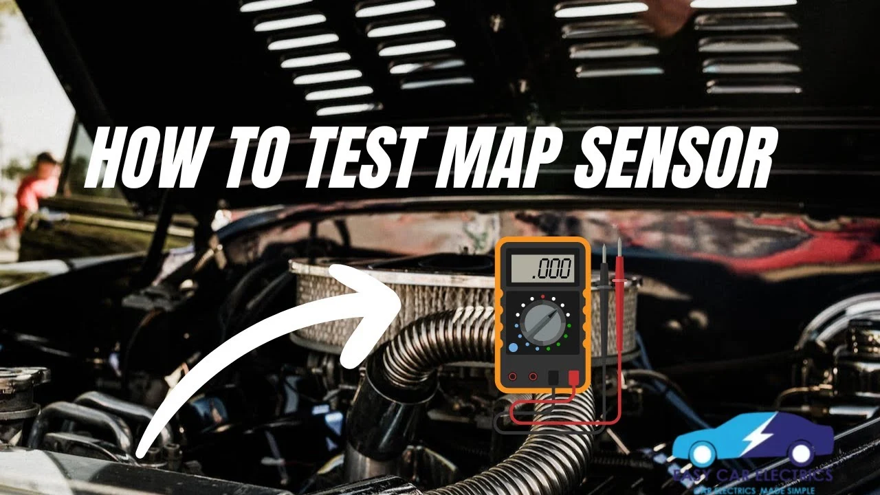
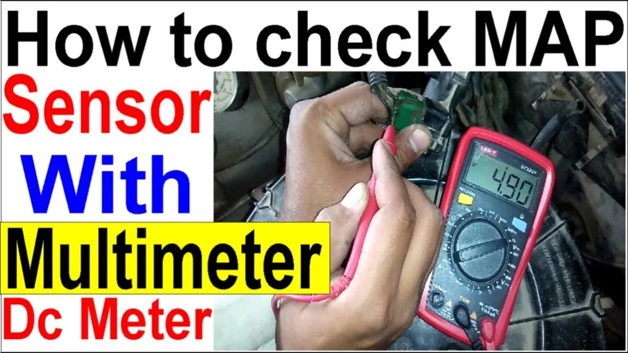
Reconnect the sensor if the procedure calls for a powered circuit test, turn the ignition on without starting the engine, and set the multimeter to DC volts. Use backprobe leads at the connector so the terminals remain connected during the test. Identify the reference and ground terminals from the wiring diagram.
Measure between the 5-volt reference terminal and the sensor ground terminal. Many systems will show close to 5 volts, but the acceptable range must come from the vehicle’s specifications. A reading near zero suggests a short, an open circuit, a power-supply problem, or an engine-control-module issue—not automatically a bad MAP sensor.
Next, check the sensor ground. Place the positive meter lead on the battery positive terminal and the negative lead on the sensor-ground terminal while the circuit is powered. The reading should show that the ground can carry current; a noticeable voltage drop indicates unwanted resistance in the ground circuit.
Some manufacturers specify a different ground-drop test, so follow that procedure when available.
Do not pierce insulation unnecessarily. A puncture can admit moisture and create a future wiring fault. If a terminal must be tested from the front, use the correct terminal probe and avoid spreading the connector contact.
Step 4 Measure the signal with the engine off
With the ignition on and the engine off, measure the signal terminal against the sensor ground. At this point the pressure in the intake manifold should be close to the surrounding atmospheric pressure, so the reading should correspond to the key-on, engine-off value listed in the service information or scan-tool data.
The exact voltage is not universal. Many analog MAP sensors produce a relatively higher signal at atmospheric pressure and a lower signal as vacuum increases, but the range depends on the sensor and the pressure at your location. Altitude and weather can change the absolute pressure, so do not reject a sensor solely because your reading does not match a generic internet value.
Compare the voltage with a scan tool if possible. The scan tool may display MAP in kilopascals, or kPa, which is an absolute-pressure measurement. With the engine off, the displayed pressure should be reasonably close to local barometric pressure after accounting for altitude and sensor accuracy.
Step 5 Check the running signal for a smooth response
Start the engine and let it idle only if the vehicle is safely parked, in the correct gear, and adequately ventilated. Measure the MAP signal again or watch the live-data value. Engine vacuum at idle should lower the intake pressure, so the signal or pressure reading should change clearly from the key-on, engine-off condition.
Briefly raise engine speed while watching the reading, then let it return to idle. A healthy sensor and circuit usually show a quick, smooth change toward higher pressure when throttle opens and a return toward the idle value when the throttle closes. The value should not freeze, jump erratically, or drop out as the engine moves or the harness is gently positioned.
Do not blip the throttle repeatedly in an enclosed garage. If the signal changes only when the connector or harness is moved, suspect a terminal or wiring fault. If the voltage is stable but the engine vacuum is abnormal, diagnose the engine condition before replacing the sensor.
Step 6 Apply controlled vacuum when the sensor design allows it
A hand vacuum pump can provide a more controlled response test, but use it only if the sensor has an accessible vacuum port and the manufacturer permits this method. Disconnect the hose or remove the sensor as directed, attach the pump without stressing the port, and monitor the signal with the sensor electrically connected.
Apply vacuum gradually while watching the multimeter or scan-tool value. The reading should change progressively and hold reasonably steady when the applied vacuum is held. Release the vacuum and confirm that the signal returns toward its starting value.
A flat reading, sudden jumps, failure to hold, or a value that does not return indicates a possible sensor, hose, or connection problem.
Some MAP sensors are sealed directly to the manifold and are not designed for an external pump connection. Do not force a hose onto an electrical opening or apply pressure beyond the specifications. If the service information does not describe a vacuum test, use the key-on and running tests instead.
Step 7 Compare the results and decide what the evidence supports
Bring the readings together before buying a part. A valid diagnosis should account for the circuit supply, ground quality, pressure path, signal behavior, and engine condition. Use this pattern as a guide, then confirm it against the wiring diagram and factory specifications.
A useful way to approach how to check map sensor is to check your progress after each stage.
| Observed result | What it suggests |
|---|---|
| No 5-volt reference | Reference-wire short or open, shared sensor fault, power supply issue, or control-module problem |
| Good reference but poor sensor ground | Ground wire, terminal, connector, or ground circuit resistance |
| Good power and ground, fixed signal | Failed sensor, blocked pressure passage, signal-wire fault, or incorrect test terminal |
| Signal changes but engine vacuum is low | Possible vacuum leak, valve-timing issue, restricted exhaust, or mechanical engine problem |
| Intermittent signal when harness moves | Loose terminal, broken conductor, corrosion, or damaged connector |
If the reference, ground, and signal all behave correctly and the live data agrees with actual engine conditions, the MAP sensor is less likely to be the cause. An engine that runs poorly can create unusual manifold pressure, which the sensor may be reporting accurately.
Step 8 Repair the confirmed fault and verify the result
Repair only the fault supported by your tests. Replace a split vacuum hose, clean or repair a corroded terminal using the proper automotive method, restore a damaged wire, or replace the sensor if it fails the specified response test with a confirmed circuit and pressure path.
After the repair, reconnect every hose and electrical connector, make sure the sensor is sealed correctly, and clear diagnostic trouble codes only after recording them. Start the engine and recheck the key-on, engine-off and idle values. The reading should now agree with the vehicle’s expected behavior and remain stable.
Complete a cautious road test if the vehicle is safe to drive and local conditions allow it. Watch for restored idle quality, normal throttle response, and the absence of the original symptom. Recheck for returning codes after the drive; a code that comes back points to an unresolved fault rather than a successful repair.
What the MAP Sensor Reading Actually Means
A MAP sensor measures absolute pressure inside the intake manifold, not vacuum directly. With the engine off, manifold pressure is near the surrounding atmospheric pressure. At a warm idle on a healthy engine, the closed throttle creates lower manifold pressure, commonly described as higher vacuum.
Because it measures absolute pressure, a MAP reading does not behave like a gauge that simply starts at zero. A scan tool may show a higher kPa value with the engine off and a lower kPa value at idle. A multimeter usually shows the opposite general trend on many analog sensors: higher signal voltage at higher pressure and lower voltage at higher vacuum.
This relationship explains why knowing how to check map sensor output requires comparing conditions rather than memorizing one number. The key-on, engine-off reading establishes a pressure baseline; the running reading shows whether the sensor responds to the vacuum created by the engine.
Why the engine may set a MAP-related code even when the sensor is good
The engine-control module compares MAP information with throttle position, engine speed, airflow, oxygen-sensor feedback, and other inputs. A vacuum leak, incorrect valve timing, restricted exhaust, low compression, or an intake problem can make those values disagree.
For example, a large vacuum leak can produce higher-than-expected manifold pressure at idle. The MAP sensor may correctly report that pressure, while the engine computer sets a performance or correlation code. Replacing the sensor without checking the engine’s actual vacuum condition may leave the problem unchanged.
How to Confirm the Diagnosis Without Guessing
Verification means checking that the measured behavior makes sense in more than one operating condition. A single good reading at the connector is not enough, especially when the original complaint is intermittent or occurs only while driving.
Use live data as a comparison, not a substitute for testing
A scan tool can show the MAP value, calculated load, engine speed, and related sensor information while the engine runs. Compare the MAP value with the key-on, engine-off baseline and observe whether it responds immediately when the throttle changes.
Live data is useful for finding a dropout that a stationary meter test may miss, but the scan tool is receiving a processed signal from the vehicle computer. If the scan value looks implausible, confirm the electrical signal at the sensor and inspect the circuit before assuming the display identifies the failed component.
Check for related faults before clearing codes
Record all stored and pending diagnostic trouble codes before clearing anything. Codes involving fuel trim, throttle position, barometric pressure, ignition misfire, or sensor correlation can change the direction of the diagnosis.
- Inspect intake boots and vacuum hoses for leaks.
- Check whether the air filter housing and ducting are properly assembled.
- Look for oil or water contamination at the MAP connector.
- Compare engine vacuum or MAP pressure with the engine’s mechanical condition.
- Confirm that the battery voltage and charging system are not causing unstable sensor readings.
Troubleshooting Common Testing Mistakes
MAP testing is straightforward when the terminals and pressure conditions are identified correctly. Most misleading results come from testing the wrong wire, using a generic specification, or overlooking a physical problem between the sensor and the intake manifold.
The voltage is close to zero on every test
First confirm that the meter is set to DC volts and that its leads work on a known power source. Then verify the terminal identification. If the reference is missing, trace the reference circuit and check other sensors that share it; one shorted sensor can pull down a shared 5-volt supply.
If the reference is present but the signal remains at zero, inspect the signal wire for a short to ground and check the sensor ground under load. Do not replace the MAP sensor until those circuit checks are complete.
The reading is stuck near the reference voltage
A signal that stays near the reference voltage can result from an open signal wire, a poor sensor ground, an unplugged sensor, or an internal sensor fault. Check the connector from both sides and gently inspect for a backed-out terminal.
Never bridge terminals with a screwdriver or jumper wire to “see what happens.” That can damage the control module or create a second fault that makes the original diagnosis harder.
The reading changes, but the engine still runs badly
A changing signal shows that the sensor is responding, but it does not prove that the output is accurate. Compare the pressure with the engine’s actual vacuum condition and inspect for intake leaks, ignition problems, fuel-delivery issues, and mechanical timing faults.
The sensor passes while parked but fails on the road
Look for vibration-sensitive wiring, a loose connector, heat-related failure, or a vacuum hose that collapses or leaks under movement. Secure the vehicle, reproduce the symptom only when safe, and monitor live data while gently moving the harness. Do not perform a roadside or moving test that requires holding a meter near rotating parts.
MAP Sensor Testing FAQs
These answers cover the questions that commonly arise when a beginner is deciding whether the sensor, its wiring, or the engine is responsible for a problem.
Can I check a MAP sensor without a multimeter?
Yes, a scan tool can show whether the MAP value changes between key-on, engine-off and running conditions, and a visual inspection may reveal a damaged hose or connector. A multimeter is still the better way to separate a bad sensor from a missing reference voltage or poor ground.
What should a MAP sensor read with the engine off?
With the ignition on and engine off, the MAP reading should be close to local atmospheric pressure on a scan tool, while the signal voltage should match the vehicle’s specified key-on, engine-off range. Altitude affects pressure, so use the manufacturer’s specifications rather than one universal voltage.
Does a bad vacuum hose cause the same symptoms as a bad MAP sensor?
It can. A cracked, loose, blocked, or incorrectly routed hose changes the pressure reaching the sensor and can cause poor starting, rough idle, hesitation, and MAP-related trouble codes. Inspect the hose and sensor port before replacing the electrical part.
Should I clean a MAP sensor?
Follow the vehicle maker’s instructions. If cleaning is allowed, use only a product specifically approved for the sensor and avoid touching the sensing element or forcing liquid into the housing. Do not use a wire brush, carburetor cleaner, or compressed air unless the service procedure explicitly permits it.
Can I drive with a suspected bad MAP sensor?
A short trip for diagnosis may be possible if the vehicle is running safely, but avoid driving if it stalls, lacks power in traffic, misfires severely, or smells strongly of fuel. An incorrect load signal can affect fueling and catalytic-converter temperature, so have the vehicle professionally diagnosed when the test results are uncertain.
Confirm the Cause Before Replacing the Sensor
Knowing how to check map sensor operation means checking the complete system: the pressure passage, connector, 5-volt reference, sensor ground, signal response, and engine condition. The most convincing result is a smooth, plausible change as intake pressure changes, backed by a healthy circuit and a scan-tool value that fits the engine’s operating state.
After any repair, reconnect the system carefully, repeat the key-on and running checks, and confirm that the original code or symptom does not return. If the readings conflict or the engine’s vacuum condition is abnormal, stop replacing parts and continue with a broader engine diagnosis or seek qualified help.