How to Check Temperature Sensor by Multimeter: Detailed Guide
A temperature sensor can fail without looking damaged. A dashboard may show an implausible reading, an appliance may run too hot, or an HVAC controller may display an error even though the sensor’s connector appears clean. A digital multimeter can help separate a bad sensor from a loose connection or a problem elsewhere in the circuit.
The most common test is a resistance check with the sensor disconnected and the equipment powered off. Many temperature sensors are thermistors, meaning their resistance changes as temperature changes. A cold sensor and a warmed sensor should therefore produce different readings, but the correct value depends on the sensor type and its specifications.
In this guide, you will learn how to check temperature sensor by multimeter without applying meter voltage to a powered control circuit. You will identify the sensor, isolate it safely, measure resistance, perform a simple temperature-change check, compare the result with reliable specifications, and recognize when the fault is more likely to be in the wiring or control module.
At a glance
- Disconnect the sensor and switch equipment power off before measuring resistance.
- A resistance reading is meaningful only when compared with the sensor’s specifications and current temperature.
- An open circuit, near-zero resistance, unstable reading, or poor temperature response can indicate a fault.
How to check temperature sensor by multimeter safely and accurately
The method below is designed primarily for two-wire resistance-based sensors, especially NTC thermistors used in vehicles, HVAC equipment, appliances, and electronic controls. An NTC thermistor has lower resistance as temperature rises. Some sensors use PTC behavior, RTD elements, a built-in electronic circuit, or a simple on/off switch, so identification and specifications come before interpretation.
Tools you will need
- A digital multimeter with resistance and voltage functions, for measuring the sensor without guessing its condition
- Equipment documentation or a manufacturer-provided resistance-versus-temperature chart
- Optional: a non-contact thermometer or a container of warm water for a controlled temperature-change check
- Optional: back-probe leads or small insulated test leads, used only when the connector design permits safe contact

Step 1 Identify the sensor type and find its specifications
Locate the component’s identification label, service-manual reference, wiring diagram, or replacement-part information. Count the wires and note where the sensor is installed. A two-wire probe is often a passive thermistor or RTD, while a three-wire or four-wire device may be an RTD, a powered sensor, or a sensor with signal conditioning.
Look for a specification such as “10 kΩ at 25°C” or a resistance table showing values at several temperatures. The phrase “10 kΩ at 25°C” does not mean the sensor should read 10,000 ohms at every temperature; it means that value applies at the stated reference temperature, usually 25°C or 77°F.
If the sensor is a simple thermal switch, it may show continuity below or above a specified temperature rather than a smoothly changing resistance. If it has three or more wires, do not assume that a resistance test across any two pins is valid. Use the equipment documentation to identify the signal, ground, and supply terminals first.
Step 2 Make the equipment safe and expose the connector
Turn the equipment off and disconnect its power source before testing resistance. Unplug a household appliance, remove the vehicle key and follow the manufacturer’s battery-disconnection procedure when appropriate, or isolate the correct circuit according to the service instructions. Never measure resistance on a circuit that is energized.
Let hot components cool enough to handle safely, and avoid testing near moving parts, flames, refrigerant lines, or exposed high voltage. Some appliances contain capacitors that can retain a charge after power is removed. Stop if the service procedure requires opening a high-voltage section or if you cannot verify that stored energy has been discharged.
Find the sensor connector rather than piercing the insulation unnecessarily. Inspect the plug, terminals, and nearby wiring for corrosion, moisture, broken insulation, crushed sections, or a connector that is not fully latched. A visibly damaged connector can cause the same symptoms as a failed sensor and should be corrected or tested separately.
Important
Do not use resistance or continuity mode on a powered circuit. If the equipment contains exposed mains voltage, high-voltage ignition, large capacitors, or another hazard you cannot confidently isolate, stop and use a qualified technician.
Step 3 Disconnect the sensor from the circuit
Separate the sensor connector from the wiring harness or control board. Testing with the sensor still connected can include parallel paths through the controller, producing a reading that does not belong to the sensor alone. Hold the connector by its body, release its locking tab, and do not pull on the wires.
Once disconnected, identify the sensor-side terminals. Keep the equipment-side connector away from metal objects and moisture. If the sensor has only two terminals, those are normally the points used for the resistance test.
For a three-wire or four-wire device, pause and confirm the correct terminal arrangement before touching the meter probes to it.
Step 4 Set up the multimeter for resistance
Insert the black lead into the meter’s COM socket and the red lead into the socket marked for voltage, resistance, and often continuity. Select resistance mode, shown by the omega symbol (Ω), rather than current mode. If the meter is not autoranging, choose a range that is higher than the expected sensor value; for a 10 kΩ thermistor, a 20 kΩ or 200 kΩ range may be appropriate depending on the meter.
Touch the two probe tips together briefly. The display should show a value close to zero, often a small fraction of an ohm, or the meter may beep in continuity mode. This confirms that the leads and selected function are behaving normally.
A small lead resistance is normal, but a reading that stays at “OL” with the probes touching indicates a meter, lead, or setting problem.
Step 5 Measure the sensor at its current temperature
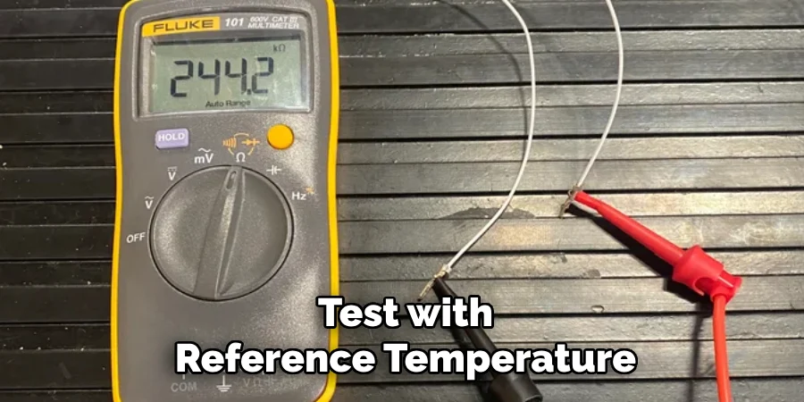
Touch one probe to each sensor terminal. Maintain firm contact without forcing the probes into a sealed connector or spreading its terminals. Wait for the display to settle, then record the resistance, the meter range, and the approximate sensor temperature.
For example, write down “8.7 kΩ at about 20°C” rather than recording only “8.7.”
For a typical NTC thermistor, a room-temperature reading in the general neighborhood of its rated value may be reasonable, but the exact acceptable range must come from the manufacturer’s chart. A 10 kΩ sensor at 25°C can legitimately read a different value in a cool garage, near a warm engine, or in your hand. A useful way to approach how to check temperature sensor by multimeter is to check your progress after each stage.
Do not use the continuity beep alone as a pass/fail test. A thermistor can have continuity and still be far outside its correct resistance range. Continuity mode is useful for finding a completely open connection, not for confirming the accuracy of a temperature-dependent component.
Check your result
A useful initial result is a stable resistance reading that is plausible for the sensor’s measured temperature. “OL,” a nearly zero reading, or a value far outside the manufacturer’s chart needs further investigation.
Step 6 Change the sensor temperature and watch the reading
A healthy passive sensor should respond in a predictable direction. For an NTC thermistor, gently warm the sensing tip with your fingers or place the tip in warm water while keeping the connector and meter leads dry. The resistance should decrease smoothly as the sensor warms.
For a PTC device, the resistance should increase instead.
Use a thermometer if the specification chart requires a particular temperature. A warm-water test is useful only when the sensing element is designed to contact water and its connector is kept completely above the waterline. Do not immerse a sensor that is not sealed, and do not use boiling water unless the manufacturer explicitly permits that temperature.
Move the sensor gently and observe the display. A gradual, repeatable change is more informative than one isolated number. A reading that jumps when the wire or connector is moved can indicate an intermittent connection, damaged lead, or cracked sensor body.
Step 7 Compare the readings with the correct chart or service data
Place your recorded resistance and temperature beside the manufacturer’s resistance-versus-temperature table. Compare values at the nearest listed temperatures rather than expecting an exact match. Thermistors often change substantially over a relatively small temperature range, so a difference of several degrees can matter.
If the sensor is an RTD, the expected relationship is different. A common platinum RTD is specified by a nominal resistance at 0°C, such as 100 Ω or 1,000 Ω, and its value rises as temperature increases. Do not judge an RTD by a thermistor chart or judge a PTC sensor by an NTC chart.
A sensor passes this basic test when its resistance is within the documented tolerance and changes in the documented direction without abrupt jumps. If no specifications are available, the test can still reveal an obvious open circuit, short circuit, or unstable response, but it cannot prove that the sensor is accurately calibrated.
Step 8 Test the wiring separately when the sensor reading seems reasonable
Reconnect the sensor only after completing the isolated resistance test. If the sensor’s readings are plausible but the equipment still reports a temperature fault, inspect the harness and connector next. With power removed, use the wiring diagram to check continuity from the sensor connector to the control module, one conductor at a time.
For a wiring continuity check, place one meter probe at the sensor-side terminal and the other at the matching terminal at the controller. A healthy conductor should show very low resistance, but the acceptable limit depends on the equipment and wire length. Also check for an unintended short between each signal wire and ground or between adjacent conductors.
Do not rely on a continuity result made through an unknown circuit path. Disconnect the relevant connectors as directed by the service information, and avoid applying a meter’s test voltage to a circuit containing delicate electronics unless the manufacturer allows it.
Step 9 Reconnect the sensor and verify the operating result
After the resistance and wiring checks, reconnect the plug until its locking feature is fully engaged. Restore power according to the equipment’s normal procedure, then observe the displayed temperature, fault code, or operating behavior as the equipment warms or cools.
A successful verification is not merely “the meter beeped.” The sensor should produce a believable temperature or control response, the fault should not immediately return, and the reading should change in the expected direction during a real temperature change. Some controllers store fault codes, so clearing a code may require a scan tool or manufacturer-specific reset procedure.
If the equipment now behaves normally, secure the harness away from heat, sharp edges, fans, belts, and moving linkages. If the same fault returns, turn the equipment off again and continue with the troubleshooting checks below rather than repeatedly replacing the sensor. Understanding how to check temperature sensor by multimeter also means recognizing the limits of the method.
What the multimeter reading means
The measurement is meaningful only in context. Resistance depends on sensor design, temperature, tolerance, and sometimes the condition of the connector or wiring. The table below describes common patterns, but the service specification remains the final authority.
| Meter result | Likely meaning |
|---|---|
| OL or infinite resistance | An open sensor element, broken wire, disconnected terminal, or poor probe contact |
| Nearly 0 Ω | A shorted sensor, shorted wiring, contaminated connector, or incorrect test points |
| Stable but far outside the chart | A failed or incorrect sensor, or a temperature different from the assumed test temperature |
| Resistance changes smoothly in the expected direction | Evidence that the passive sensing element is responding, though it does not prove absolute accuracy |
| Reading jumps or cuts out when moved | An intermittent element, terminal, connector, or wire fault |
Why ambient temperature matters
A temperature sensor does not have one universal “good” resistance. A 10 kΩ NTC thermistor is commonly named for its approximate resistance at a reference temperature, but its value can be much higher when cold and much lower when warm. The label alone is not enough to establish a pass or fail.
Allow the sensor and the surrounding air to reach a fairly stable condition before taking the first reading. If the component was removed from a hot machine, record that it is still warm or let it cool before comparing it with a room-temperature value.
Why a good resistance test may not prove the whole system works
The meter checks the sensor element at a very small test current. The equipment may use a different circuit, a reference voltage, a pull-up resistor, or a controller input to interpret the sensor. A sensor can measure plausibly while a corroded terminal, missing reference voltage, damaged ground, or failed control input prevents the system from reading it correctly.
When the sensor is connected and powered, a voltage test may be appropriate, but only with the correct wiring diagram and specified test points. Do not apply a guessed voltage to a sensor terminal. If the sensor is an active digital device, a resistance test may give an unhelpful result or risk misleading conclusions.
Troubleshoot readings that do not make sense
Unexpected results usually come from one of four sources: the wrong sensor type, the wrong test points, a poor connection, or a genuinely failed component. Work from the least invasive explanation first and repeat the measurement with the sensor isolated before buying a replacement.

The meter displays OL
Confirm that the probes touch clean, separate sensor terminals and that the meter is in Ω mode. Touch the probes together to verify the leads. If the leads show near-zero resistance together but the isolated sensor still shows OL, the sensor element or its internal connection is open.
Inspect the terminal crimp and the short wire entering the sensor body. A broken conductor can open the circuit even when the plastic housing looks undamaged. If the sensor is a thermal switch, however, an open reading may be normal at the current temperature; check its specified switching temperature.
The meter shows almost zero ohms
Make sure the probes are not touching each other or contacting a common metal shell that is not a sensor terminal. If the reading remains near zero on the correct terminals, the sensor may be shorted internally. A short in the harness can produce the same result, which is why the sensor must be disconnected from the harness for the first test.
The resistance is plausible but the equipment still shows a fault
Check connector fit, terminal tension, corrosion, moisture, and wiring continuity. Look for a broken wire close to the connector, where repeated flexing can damage the conductor under intact insulation. If wiring and sensor values are correct, the problem may involve a reference voltage, controller input, software logic, or another related component.
The reading is unstable
Hold the probes steady and clean only the accessible metal contact surfaces using a method approved for that equipment. Then gently flex the sensor lead and connector while watching the display. A repeatable interruption points toward a damaged lead or terminal; a jump caused by touching the sensing body may indicate a loose internal element.
The value changes in the wrong direction
Check whether the sensor is PTC rather than NTC, and confirm the temperature actually changed at the sensing tip. If documentation says the device should decrease in resistance as it warms but your isolated test shows a reliable increase, the sensor may be the wrong part or defective.
Beginner questions about temperature sensor multimeter tests
These questions address common uncertainties that can make a simple resistance test misleading. When a model-specific service manual conflicts with a general rule, follow the model-specific procedure.
Can I test a temperature sensor without removing it?
You can sometimes probe the back of its disconnected connector, but the sensor should be electrically isolated for a trustworthy resistance measurement. Testing it while connected can include the resistance of other circuit components and may produce a false value.
What resistance should a temperature sensor have?
There is no single correct value. The expected resistance depends on whether the device is an NTC thermistor, PTC thermistor, RTD, or thermal switch, as well as its current temperature. Use the manufacturer’s chart or service specification.
Should a temperature sensor have continuity?
A passive sensor usually has a measurable resistance, so a meter may beep if its continuity threshold is high enough. That beep does not confirm that the value is correct. An RTD or thermistor should be checked in resistance mode, while a thermal switch must be judged by its specified open or closed state at a particular temperature.
Can I test a three-wire temperature sensor with resistance mode?
Possibly, but not by guessing. Three-wire devices may use a special RTD arrangement or may include an active circuit that needs power. Identify the terminals and test procedure from the wiring diagram before measuring between pins.
Can touching the sensor change the reading?
Yes. Your fingers can warm a small sensor enough to change its resistance, especially an NTC thermistor. Hold the insulated portion of the probe and record the approximate temperature so the reading can be compared fairly with the specification.
Confirm the fault before replacing the sensor
Learning how to check temperature sensor by multimeter gives you a practical way to distinguish an obvious open circuit, short circuit, unstable element, or incorrect temperature response from a wiring problem. The essential sequence is to identify the sensor, remove power, disconnect it, measure resistance, change its temperature carefully, and compare the results with the correct specifications.
A plausible resistance reading is useful evidence, not an absolute guarantee. If the sensor passes but the equipment still reports a fault, investigate the connector, harness, reference voltage, and control circuit rather than installing parts at random. Stop when the procedure reaches an energized or high-voltage section you cannot safely verify, and have that portion tested by a qualified technician.