How to tell if engine coolant temperature sensor is bad: Test
A coolant temperature sensor can fail in ways that look like several unrelated problems. A hard cold start, poor fuel economy, a cooling fan that runs constantly, an inaccurate temperature gauge, or a check-engine light may all point toward the sensor—but they can also come from damaged wiring, low coolant, a thermostat problem, or another engine-control fault.
The good news is that you can often narrow down the cause without immediately replacing parts. A visual inspection, a scan-tool reading, and a few multimeter checks can show whether the sensor is reporting a believable temperature and whether its circuit has power, ground, and a changing signal.
This guide explains how to tell if engine coolant temperature sensor is bad on a typical modern vehicle. It also shows how to separate a bad sensor from a connector or wiring problem, when resistance testing is useful, and when to stop because the engine or cooling system is too hot to work on safely.
At a glance
- A cold-engine scan reading should be close to the surrounding air temperature.
- A sensor code does not prove the sensor itself has failed; the connector and wiring can produce the same symptoms.
- Never remove a pressurized radiator or expansion-tank cap while the engine is hot.
How to tell if engine coolant temperature sensor is bad
The most reliable beginner-friendly method is to test the sensor in context rather than relying on one resistance number. First confirm the symptom, then compare the scan-tool temperature with the actual engine condition, inspect the circuit, and finally test the sensor against the specifications for that vehicle.
Tools you will need
- An OBD-II scan tool with live data, to read coolant temperature and diagnostic trouble codes
- A digital multimeter, to check voltage, continuity, and sensor resistance
- The vehicle service information or repair manual, for the correct pinout and resistance specifications
- A flashlight and small inspection mirror, to examine the connector and wiring
- Optional: an infrared thermometer, to compare surface temperatures without touching hot components
- Optional: insulated back-probe leads, to test the connected circuit without damaging the connector
Step 1 Confirm which temperature sensor you are testing
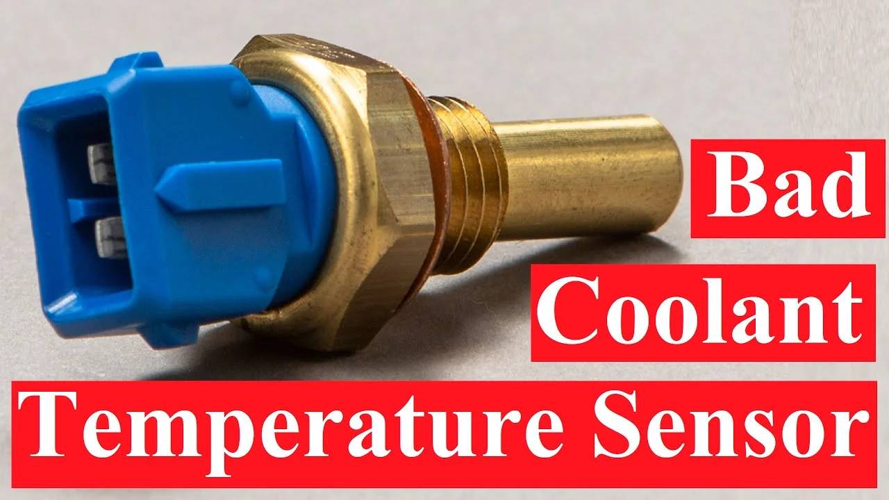
Find out whether the vehicle has one coolant temperature sensor or separate sensors for the engine computer and the dashboard gauge. Many vehicles use an engine coolant temperature sensor, often called an ECT sensor, for the engine control module. Some vehicles also have a separate coolant temperature sender for the gauge or warning light.
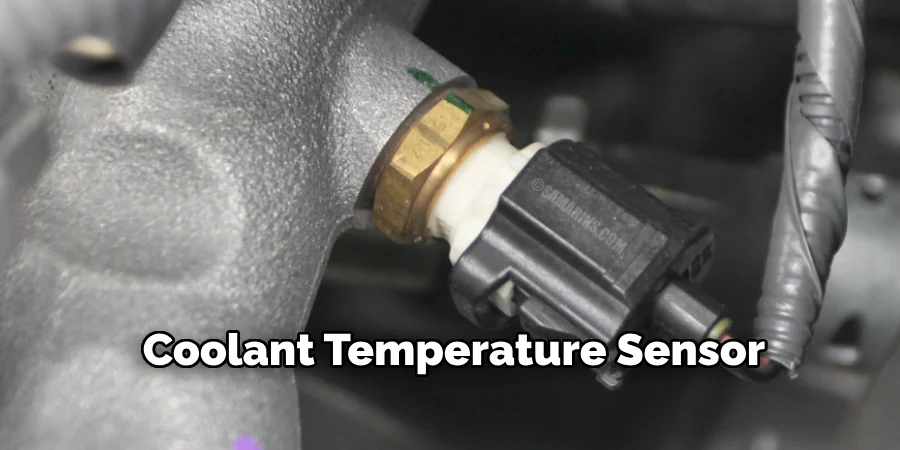
Use the owner’s manual or service information to identify the correct part. The ECT sensor is commonly threaded into the cylinder head, intake manifold, thermostat housing, or a coolant passage near the engine. It usually has an electrical connector with two or more wires.
Do not assume that the sensor near the radiator is the one that controls the engine computer.
This distinction matters because a faulty gauge sender may leave the engine computer’s temperature data normal. Conversely, a bad ECT sensor may cause drivability problems even if the dashboard gauge appears normal.
Step 2 Check the coolant level and inspect for obvious damage
Allow the engine to become completely cool before opening any coolant reservoir or inspecting parts close to the engine. Check the coolant level against the markings on the expansion tank. If the level is very low, the sensor may not be surrounded by coolant, and the temperature reading may not represent the engine accurately.
Look for coolant leaks around the sensor, thermostat housing, hoses, radiator, and reservoir. A leak can damage the connector or allow air into the cooling system. Also look for dried, crusty coolant residue, wetness, a broken sensor body, or a connector that is not fully latched.
Follow the sensor wires several inches away from the connector. Search for melted insulation, rubbing against a bracket, oil contamination, corrosion, rodent damage, or a repair made with loose twist connectors. An electrical fault near the sensor can create the same trouble codes as a failed sensor.
Important
Do not remove a radiator cap or pressurized expansion-tank cap when the engine is hot. Hot coolant and steam can cause severe burns. If the coolant level is low, repair the leak and follow the vehicle’s proper bleeding procedure before trusting temperature readings.
Step 3 Read diagnostic trouble codes before disconnecting anything
Connect the scan tool and record stored, pending, and history codes before clearing them. Codes such as P0115, P0116, P0117, P0118, and P0119 are commonly associated with coolant temperature sensor circuits, but the exact code definitions and test procedure can vary by manufacturer.
A low-input code, such as P0117, often means the control module sees a voltage lower than expected. A high-input code, such as P0118, often means it sees a voltage higher than expected. These descriptions refer to the electrical signal, not necessarily to the coolant being physically too hot or too cold.
Record freeze-frame data if your scan tool provides it. Freeze-frame data shows conditions such as engine speed, vehicle speed, load, and reported coolant temperature when the fault occurred. For example, a coolant reading of an extreme value immediately after a cold start is more suspicious than a moderately unusual reading during a hot climb.
Step 4 Compare the cold scan reading with the surrounding temperature
Leave the vehicle parked long enough for the engine to cool fully, preferably overnight. Turn the ignition on without starting the engine, connect the scan tool, and open the live-data display for engine coolant temperature.
The reported coolant temperature should be reasonably close to the temperature of the engine and surrounding air. It does not have to match a weather app exactly, but a reading far below freezing on a warm day, or an extremely hot reading from a cold engine, indicates a problem with the sensor circuit, the sensor, or the scan-data interpretation.
This check is one of the most useful ways to tell if engine coolant temperature sensor is bad because it tests plausibility before heat changes the result. A cold reading around the ambient temperature suggests that the sensor is at least responding plausibly at that moment; it does not completely prove the sensor is good.
Step 5 Watch the temperature rise while the engine warms
Start the engine and monitor the coolant temperature on the scan tool. The number should generally rise smoothly as the engine warms. The exact warm-up rate depends on outside temperature, engine size, thermostat operation, and whether the vehicle is idling or being driven.
Look for a reading that stays fixed, jumps suddenly, drops to an impossible value, or changes when the harness is gently moved. A temperature that remains near the cold reading after the engine has clearly warmed may indicate an open circuit, a sensor fault, or a thermostat that is stuck open. A temperature that immediately reports an extreme value can indicate a short circuit or open circuit, depending on the system design.
Do not use the dashboard gauge alone as your test. The gauge may be damped by the vehicle computer, meaning it stays near the middle across a broad range of actual temperatures. The scan tool usually provides more useful information for diagnosing the ECT circuit.
A useful way to approach how to tell if engine coolant temperature sensor is bad is to check your progress after each stage.
Check your result
A believable result is a cold reading near ambient temperature followed by a steady increase as the engine warms. If the value is impossible or erratic, continue with the connector and circuit checks instead of replacing the sensor immediately.
Step 6 Inspect and test the connector with the ignition off
Turn the ignition off and disconnect the sensor connector according to the vehicle’s service instructions. Do not pull on the wires. Check for green or white corrosion, pushed-back terminals, moisture, oil, a broken locking tab, or terminals that appear spread apart.
Compare the connector with the sensor pins. A loose terminal may look clean but fail to grip the pin firmly. If the connector is wet or contaminated, identify and correct the source of the contamination before installing a replacement connector or sensor.
With the connector disconnected, use the multimeter only as directed by the service information. A continuity check can help identify a broken wire, but testing continuity from the connector to the control module may require access to a specific terminal. Never connect a multimeter’s resistance function to a powered circuit.
Step 7 Measure the sensor’s resistance when it is cold
Set the multimeter to resistance, commonly marked with the omega symbol, and touch the probes to the sensor terminals. Use the correct terminals shown in the wiring diagram; a multi-pin sensor may contain more than one circuit, and testing the wrong pair can produce a meaningless result.
Record the coolant or engine temperature at the time of the test. Most ECT sensors are negative-temperature-coefficient thermistors. That means their resistance usually decreases as temperature increases, but the correct resistance at a given temperature is specific to the sensor and vehicle.
Compare your measurement with the manufacturer’s resistance chart. Do not treat a generic online value as proof because two sensors can look identical while using different resistance curves. An open circuit, displayed as OL or infinite resistance, or a near-zero reading when neither is specified, is strong evidence of a failed sensor or a problem at the terminals.
If the cold resistance is within specification, that does not end the diagnosis. A sensor can fail intermittently, become inaccurate only when warm, or work correctly while disconnected but fail under vibration or electrical load.
Step 8 Repeat the resistance check at a second temperature
If the service information provides a warm resistance specification, measure the sensor again after the engine has warmed, but only if you can do so without touching hot components or opening the cooling system. A safer alternative is to remove the sensor and place it in a controlled water bath only when the repair procedure allows removal and the sensor can be handled safely.
The resistance should change smoothly in the expected direction as temperature changes. A reading that does not change, changes in sudden jumps, or falls outside the specified range at one temperature points toward a faulty sensor.
Do not heat the sensor with an open flame, a heat gun held close to plastic parts, or boiling coolant in an uncontrolled container. If the temperature specification and removal procedure are unclear, skip this variation and use scan-data and circuit testing instead.
Step 9 Check the reference voltage and signal circuit
Reconnect the sensor if the service information calls for a connected-circuit test, then turn the ignition on without starting the engine. Identify the reference-voltage, signal, and ground terminals from the wiring diagram. Many two-wire thermistor circuits use a reference voltage supplied through the engine control module and a return signal whose voltage changes with sensor resistance.
With the correct back-probing method, compare the measured voltage with the specification. Do not force a probe into the front of a sealed connector, pierce the wire insulation unnecessarily, or short adjacent terminals together. A reading with no reference voltage may point to an open wire, a blown supply circuit, a control-module issue, or a connector problem rather than a bad sensor.
Move the harness gently while watching the scan data or meter. If the reading changes when the harness or connector moves, repair the wiring or terminal fit before replacing the sensor. This is a useful way to tell if engine coolant temperature sensor is bad when the symptom occurs only intermittently: the sensor may be sound while the connection is not.
Step 10 Compare the results and decide whether replacement is justified
Replace the sensor when its measured resistance or signal is outside the manufacturer’s specifications, the scan reading is implausible, and the wiring and connector have been shown to be sound. If the sensor readings are correct but the scan data is wrong, revisit the connector, ground, reference circuit, and control-module interpretation.
If the scan data is normal but the dashboard gauge is wrong, investigate the gauge sender, instrument-cluster circuit, or vehicle-specific communication system. If the engine overheats while the sensor reports a believable temperature, the problem may involve the thermostat, cooling fan, water pump, radiator, air in the cooling system, or a mechanical coolant leak.
Before installing a new sensor, compare its connector, thread, sealing method, and electrical specifications with the original part. Some sensors use a sealing washer; others use tapered threads or a specified sealant. Follow the manufacturer’s installation instructions rather than applying thread sealant automatically, because excess sealant can affect grounding on some designs.
Understanding how to tell if engine coolant temperature sensor is bad also means recognizing the limits of the method.
Step 11 Reassemble, clear the fault, and verify the repair
Reconnect the sensor firmly and route the wiring away from exhaust parts, belts, pulleys, and sharp edges. Restore any clips or heat shields that were removed. If coolant was lost, refill it with the correct coolant and bleed air from the system using the vehicle’s specified procedure.
Clear the trouble codes only after recording them. Start with a cold engine and confirm that the scan-tool temperature is plausible. Let the engine warm while watching for a smooth temperature change, and verify that the cooling fan, temperature gauge, and engine operation behave normally.
A successful repair is not merely the absence of a warning light immediately after clearing codes. Drive through the conditions that originally produced the symptom, then rescan for pending codes. Some readiness monitors need a complete drive cycle before the vehicle’s diagnostic system can fully evaluate the repair.
What the coolant temperature sensor does
The engine coolant temperature sensor tells the engine control module how warm the engine is. The module uses that information to adjust fuel delivery, ignition timing, idle speed, emissions controls, and cooling-fan operation.
When the engine is cold, the computer generally adds fuel and changes idle control to help the engine start and warm up. As temperature rises, those adjustments reduce. If the sensor reports a false temperature, the engine may run too rich, too lean, or with an incorrect idle strategy.

Common symptoms of a failed or inaccurate sensor
Possible symptoms include difficult starting, rough idle, poor fuel economy, black exhaust smoke, hesitation, stalling, an illuminated check-engine light, or cooling fans that run at full speed. Some vehicles may also show an inaccurate dashboard temperature reading or shift differently because transmission control can use engine temperature data.
None of these symptoms identifies the sensor by itself. For example, a stuck-open thermostat can keep the engine too cool and cause similar fuel-economy or warm-up complaints, while a vacuum leak can cause rough running without any coolant sensor problem.
Why sensor trouble codes are not conclusive
A diagnostic code identifies a condition the control module detected in a circuit or signal. It does not always identify the failed component. A corroded connector, broken reference wire, poor ground, shorted signal wire, or control-module fault can set a code that appears to name the sensor.
The code should guide the test, not replace it. That is why the cold plausibility check, wiring inspection, and specification-based resistance test are more dependable than installing a sensor based only on a code.
Troubleshooting confusing test results
Temperature-sensor diagnosis becomes easier when the result is compared with the engine’s actual condition. The table below summarizes common patterns, but the manufacturer’s wiring diagram and specifications take priority.
| Observed result | Likely direction for diagnosis |
|---|---|
| Extreme temperature on a cold engine | Check sensor circuit, connector, reference voltage, and possible open or short |
| Reading stays fixed while the engine warms | Check for a failed sensor, damaged wiring, or a scan-data problem |
| Reading changes when the harness moves | Inspect terminal tension, corrosion, and broken wires near the connector |
| Sensor resistance is out of specification | Replace the sensor after confirming the correct temperature and terminals |
| Scan temperature is normal but gauge is wrong | Investigate the gauge sender, cluster, or gauge circuit |
| Temperature rises too high with a believable scan reading | Investigate the cooling system rather than assuming the sensor failed |
When the sensor tests good but the engine still runs poorly
Check for vacuum leaks, ignition problems, fuel-pressure issues, intake-air-temperature faults, and thermostat problems. A normal ECT signal only confirms one input; it does not prove that the rest of the engine-management system is working correctly.
When the scan tool and multimeter disagree
Confirm that the meter is on the correct function and that the probes are contacting the correct terminals. Then verify the wiring diagram, sensor temperature, connector pin numbering, and scan-tool data parameter. Aftermarket scan tools can sometimes label a data item poorly or display a value from a different temperature sensor.
When to stop and get professional help
Stop if the cooling system remains pressurized after a reasonable cool-down period, coolant is leaking onto hot engine parts, access requires working near a running belt or fan, or you cannot identify the correct terminals. A professional diagnosis is also appropriate when the sensor wiring enters a sealed harness, the control module may be damaged, or the vehicle overheats rapidly.
An overheating engine can suffer serious damage even when the temperature sensor is functioning correctly. If the warning gauge reaches the danger zone, steam appears, coolant disappears, or the engine begins knocking, shut it down safely and arrange for further diagnosis instead of continuing the test drive.
Frequently asked questions
These answers address common beginner questions that come up after the initial checks.
Can I test the coolant temperature sensor without a scan tool?
Yes. You can inspect the connector and measure sensor resistance with a digital multimeter, provided you have the correct specifications and terminal identification. A scan tool is helpful because it shows whether the sensor’s reported temperature is plausible while connected to the vehicle.
What resistance should a coolant temperature sensor have?
There is no single resistance value that applies to every vehicle. The sensor’s resistance changes with temperature, and the correct curve varies by application. Use the service information for that specific vehicle and record the sensor temperature during the measurement.
Will a bad coolant temperature sensor always trigger a check-engine light?
No. A sensor can be inaccurate without exceeding the computer’s fault limits, or it can cause a symptom that has not yet set a code. Conversely, a check-engine light with an ECT-related code may be caused by wiring or a connector instead of the sensor.
Can low coolant cause a false temperature reading?
Yes. If the sensor is not covered by coolant, it may read the temperature of air or vapor instead of the coolant surrounding the engine. Low coolant also indicates a leak or another problem that should be corrected before relying on sensor readings.
Should I replace the thermostat and sensor at the same time?
Not automatically. A thermostat and an ECT sensor can produce similar warm-up symptoms, but they are different components. Test the sensor circuit and compare the actual warm-up behavior before replacing either part.
Confirm the fault before replacing the sensor
Learning how to tell if engine coolant temperature sensor is bad starts with a believable cold reading and a smooth warm-up signal, then continues with a careful inspection of the connector, wiring, and sensor specifications. A code alone is not enough to identify the failed part.
Once the sensor, circuit, and coolant condition have been checked, replace the sensor only when the test results support it. Recheck the scan data, clear and monitor the fault, and seek help if the engine overheats or the electrical diagnosis becomes uncertain.