How to Test Transmission Speed Sensor: Step-by-Step Instructions
A failed transmission speed sensor can make a vehicle shift harshly, stay in one gear, hesitate, or show an inaccurate speedometer. Those symptoms do not prove the sensor itself is bad, however. Damaged wiring, corrosion, a poor connector, low transmission fluid, or a control-module problem can produce similar behavior.
Learning how to test transmission speed sensor circuits gives you a practical way to separate a faulty sensor from a wiring or diagnostic-code problem. The most useful checks are a careful visual inspection, the correct electrical test for the sensor design, and a scan-tool comparison between the reported speed and the vehicle’s actual movement.
This guide explains how to identify the sensor, test it safely with a digital multimeter, check the harness, and confirm the result. The exact wire colors, resistance values, connector locations, and acceptable signal ranges vary by vehicle, so the factory service information remains the final authority for model-specific specifications.
At a glance
- Do not measure resistance through a powered Hall-effect sensor unless the service information specifically permits it.
- A speed sensor can test normally on the bench while its wiring fails when the engine or transmission moves.
- Confirm the diagnosis with live data or a matching wiring test before replacing the part.
How to Test Transmission Speed Sensor: A Practical DIY Method
Transmission speed sensors monitor the rotational speed of an internal shaft or another rotating component. The vehicle computer uses that information to control shifting, engine operation, cruise control, and sometimes the speedometer. A vehicle may have an input speed sensor, an output speed sensor, or both.
The safest approach is to identify the sensor and its design before connecting a meter. Some older sensors create their own alternating-current signal, while many newer sensors receive a power supply and produce a digital square-wave signal. Testing the wrong type of circuit can give a false result or damage an electronic sensor.
Tools you will need
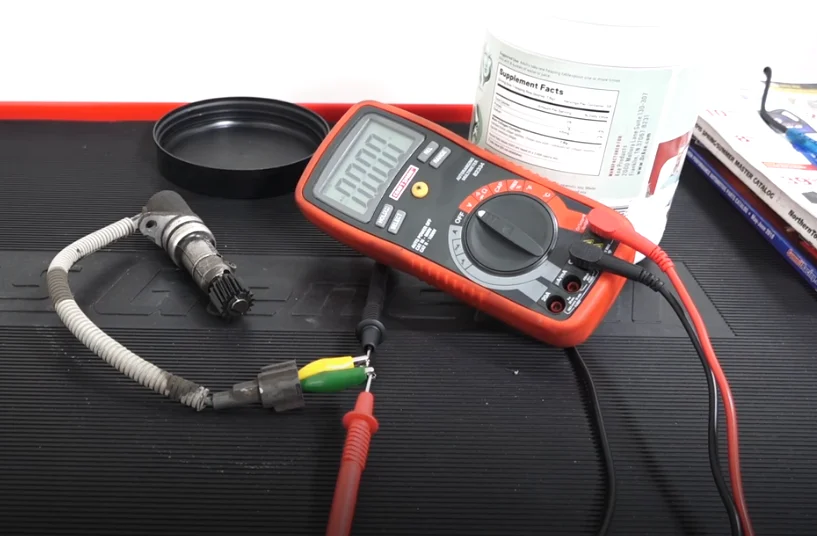
- Digital multimeter with resistance and AC/DC voltage functions
- Vehicle service information or a reliable wiring diagram for connector pinout and specifications
- OBD-II scan tool with live-data capability, optional but strongly recommended
- Back-probe leads or thin test leads, used without spreading or damaging connector terminals
- Wheel chocks, safety glasses, and gloves
Step 1 Identify the correct sensor and its electrical design
Start with the vehicle identification information, transmission type, and the diagnostic trouble code if one is present. Look up the sensor location, connector pinout, number of wires, specified resistance, and expected signal. A code such as an input-speed or output-speed sensor code points you toward a circuit, but it does not automatically condemn the sensor.
A two-wire sensor is often a passive variable-reluctance sensor. It commonly generates its own AC voltage as a toothed reluctor or tone wheel passes by. A three-wire sensor is often a Hall-effect or similar powered sensor with a supply, ground, and signal wire, although wire count alone is not conclusive.
Do not confuse a transmission speed sensor with the transmission range sensor. The range sensor tells the control module whether the selector is in Park, Reverse, Neutral, or Drive; it does not measure shaft speed. Follow the wiring diagram and the connector shape rather than guessing from location.
Helpful tip
Record the original trouble codes and freeze-frame information before clearing anything. The vehicle’s speed, engine speed, temperature, and selected gear at the moment of failure can help explain an intermittent fault.
Step 2 Park the vehicle and make the sensor safe to access
Park on a firm, level surface, select Park or the manufacturer-specified gear, set the parking brake, and chock the wheels. Turn the ignition off before unplugging a sensor. If access requires lifting the vehicle, use a properly rated jack and jack stands on approved support points; never work beneath a vehicle supported only by a jack.
Allow hot transmission components and exhaust parts to cool. Keep loose clothing, hair, and test leads away from rotating parts. Most electrical checks can be completed with the vehicle stationary, so do not run the engine or put the transmission in gear unless a service procedure specifically requires it and the necessary equipment and experience are available.
Locate the sensor and make sure you can identify its connector without confusing it with a nearby solenoid, pressure switch, or range sensor. Take a photograph before disconnecting anything. This helps you return the harness to its original routing and prevents a connector from being forced onto the wrong component.
Step 3 Inspect the sensor, connector, and harness before testing
Unplug the connector and examine both sides closely. Look for bent, pushed-back, loose, green, wet, or oil-contaminated terminals. Check the sensor body for cracks, impact damage, or transmission-fluid leakage around its mounting point.
Trace the harness several inches in both directions. Pay particular attention to areas near brackets, exhaust components, the battery, the transmission case, and engine or transmission mounts. A wire can look intact while breaking internally where vibration repeatedly flexes it.
Repair the obvious problem before interpreting electrical readings. Clean only with an electronics-safe contact cleaner when appropriate, and allow the connector to dry. Do not scrape terminals with a tool that removes their plating, and do not force a probe into a sealed connector because a loosened terminal can create a new intermittent failure.
Step 4 Measure resistance on a passive two-wire sensor
Use this test only when the wiring diagram identifies the sensor as a passive variable-reluctance type or gives a resistance specification. Keep the sensor unplugged from the vehicle harness, turn the ignition off, and set the multimeter to the resistance range. Touch the meter probes together first; the display should show a value close to zero, which confirms the leads are functioning.
Touch one probe to each sensor terminal. Compare the reading with the manufacturer’s specified range at the stated temperature. A reading of infinite resistance or “OL” usually indicates an open winding.
A reading close to zero can indicate a shorted winding, but the correct limit depends on the design, so do not reject a sensor using a generic number from another vehicle.
While watching the meter, gently flex the sensor pigtail and move the connector. The resistance should remain stable. If it jumps from a normal value to open circuit, or changes when the wire moves, the sensor lead or terminal is suspect even if the sensor itself initially measured correctly.
A useful way to approach how to test transmission speed sensor is to check your progress after each stage.
Resistance alone does not prove that a passive sensor produces a strong signal. A damaged winding, excessive air gap, damaged reluctor teeth, or metal debris on the sensor tip can allow a seemingly reasonable resistance reading while the sensor produces a weak or missing AC signal.
Step 5 Check the AC signal from a passive sensor
To test the output of a passive sensor, reconnect the meter to the two sensor terminals or use the manufacturer’s back-probe method. Set the multimeter to low-range AC voltage. The sensor must be connected in the way specified by the service information, and the transmission output or input shaft must rotate during the test.
On some vehicles, safely turning a driven wheel by hand while the transmission is in the specified condition creates enough movement for a basic check. On others, the vehicle must be driven while the meter or scan tool is monitored. Do not lift or run the vehicle unless you have the correct stands, wheel restraints, and procedure.
A hand-rotation test may show that a signal exists but may not reach the speed needed to reproduce the fault.
As the shaft rotates, the meter should show an AC signal that generally increases in frequency and often increases in voltage as speed rises. The exact value is vehicle-specific. A completely absent signal, a signal that cuts out as the harness moves, or a reading far below the service specification indicates a problem with the sensor, air gap, reluctor, or circuit.
Important
Never use an ohms test on a powered three-wire sensor unless the service information explicitly calls for it. Connecting a resistance meter to the wrong terminals can damage the sensor or the control circuit. Identify power, ground, and signal first.
Step 6 Verify power, ground, and signal on a powered sensor
For a Hall-effect or other powered sensor, reconnect the vehicle battery and turn the ignition to the position specified by the service information, usually without starting the engine. Back-probe the connector carefully. Do not disconnect the sensor if the test requires the control module to provide the reference voltage.
Measure the supply voltage between the sensor’s power and ground terminals. Many systems use a regulated reference or supply, but the expected value may differ by vehicle. A missing supply voltage means you should test the fuse, power feed, control module, and related wiring before replacing the sensor.
Check the ground by measuring voltage between the sensor ground and the battery negative terminal while the circuit is powered. A good ground should show very little voltage difference. A high reading suggests excessive resistance in the ground wire, connector, or ground point.
A voltage-drop test under the circuit’s operating load is more useful than relying only on continuity with the power off.
The signal wire may switch between low and high voltage as the shaft turns. A basic multimeter may display an unstable average rather than clearly showing each pulse. If the scan tool shows a changing speed while the multimeter reading seems vague, the sensor may be working; an oscilloscope is the better instrument for viewing waveform quality.
Step 7 Test the harness between the sensor and control module
If the sensor has the correct resistance or signal but the vehicle computer reports no speed, inspect the circuit between the sensor connector and the transmission control module or engine control module. Disconnect the battery or modules only as directed by the service information, because some vehicles require specific procedures to prevent memory loss or damage.
With the circuit unpowered and the relevant connectors disconnected, check each wire for continuity end to end. Then check for unwanted continuity between each signal wire and ground, power, or another circuit. The wiring diagram must guide this test; a shared ground or shield can make an apparently unexpected connection normal.
Move the harness while watching the meter. A stable reading with the harness still does not rule out a vibration-related failure. Look for stretched wires, water entering from above, terminals that back out of the connector, and poor repairs made with twisted wires or unsuitable crimp connections.
Step 8 Compare live data with actual vehicle movement
Connect an OBD-II scan tool that can display transmission input speed, output speed, or vehicle speed. Start with the vehicle stationary. The appropriate speed parameter should normally read zero or close to zero, though a small amount of noise may appear.
If the service procedure permits a controlled road test, monitor the relevant live-data value while driving in a safe area and obeying local laws. The displayed speed should rise smoothly as the related shaft turns. It should not drop to zero randomly, remain fixed while the vehicle moves, or disagree sharply with other known speed signals without an explanation.
Understanding how to test transmission speed sensor also means recognizing the limits of the method.
Compare the scan data with the symptom. If input speed changes but output speed remains zero, the problem may be at the output sensor, its circuit, or a mechanical component. If both sensor values disappear together, consider a shared power, ground, connector, control-module, or transmission-mechanical issue rather than replacing both sensors immediately.
Clear codes only after recording them, completing the checks, and repairing the confirmed fault. A short verification drive should show that the original symptom and code do not return. Some codes require several drive cycles or specific operating conditions before the control module sets or clears them.
What the Test Results Actually Mean
Electrical measurements are most useful when they agree with the symptoms and live data. A sensor with an open circuit, a short outside specification, no output while the shaft rotates, or a missing signal with known-good power and ground is a strong replacement candidate. Even then, inspect the tone wheel and sensor mounting area before installing a new part.
A normal sensor reading does not eliminate a mechanical cause. Excessive sensor clearance, a damaged reluctor tooth, metal particles on a magnetic sensor, a slipping transmission component, or a problem inside the transmission can interrupt the speed information. The sensor may be accurately reporting a problem rather than causing it.

| Observed result | Useful next direction |
|---|---|
| Open or shorted passive sensor winding | Compare with the specification, then replace the sensor if confirmed. |
| No supply or poor ground at a powered sensor | Trace the fuse, power, ground, connector, and control-module circuit. |
| Good sensor output but no scan-tool speed | Check signal wiring, terminals, module input, and configuration. |
| Intermittent signal when the harness moves | Repair the harness or terminal and retest under the same movement. |
| Correct electrical tests but persistent shifting fault | Investigate reluctor condition, fluid condition, mechanical faults, and other codes. |
How to Confirm the Repair
After repairing a wire or replacing a sensor, reconnect every connector until its lock engages and secure the harness away from heat and moving parts. If the sensor uses an O-ring, lubricate or replace it according to the service information. Do not overtighten the retaining bolt or leave debris on a magnetic sensor tip.
Scan for codes again and review live data with the vehicle stationary. The speed value should be stable at rest. During a permitted road test, verify smooth signal changes, normal shifting, and the return of the speedometer or cruise-control function if those systems were affected.
A repair is not confirmed merely because the warning light turns off after clearing codes. The useful confirmation is that the circuit has the correct electrical conditions, the live-data signal follows actual movement, and the original symptom does not return under comparable conditions.

Troubleshooting Common Mistakes
The most common mistake is assuming every speed sensor is tested the same way. A passive sensor may be checked for resistance and AC output, while a powered sensor requires supply, ground, and switching-signal tests. Always begin with the wiring diagram.
The resistance reading is normal, but the code returns
Resistance checks only the sensor winding at rest. Check the AC output while the shaft rotates, inspect the sensor tip and reluctor, and perform a wiggle test on the harness. An intermittent open may appear only when the transmission moves on its mounts.
The scan tool shows zero speed all the time
First confirm that the scan tool is displaying the correct parameter. Then check sensor power and ground if it is a powered design, or check for AC output if it is passive. If the sensor signal reaches the connector but not the control module, focus on the signal wire and terminals.
The vehicle has several transmission-related codes
Read all codes before repairing anything. A shared power or ground problem can create multiple sensor codes, and a low-voltage event can store unrelated faults. Address a confirmed supply or communication problem before replacing several sensors.
The new sensor did not solve the shifting problem
Recheck the connector, sensor seating, air gap, and harness routing. Then consider transmission fluid level and condition, mechanical damage, other speed signals, and control-module faults. A speed sensor code can be a consequence of an internal transmission problem rather than the root cause.
Transmission Speed Sensor Testing FAQs
These questions cover the points that most often confuse beginners when testing a vehicle speed circuit.
Can I test a transmission speed sensor without removing it?
Usually, yes. Resistance, power, ground, wiring, and live-data tests can often be performed with the sensor installed. Removing it may be necessary only for a close inspection, replacement, or a procedure that requires bench testing.
What does a bad transmission speed sensor feel like?
Possible symptoms include harsh or delayed shifting, staying in one gear, an inaccurate speedometer, cruise-control failure, reduced engine performance, or an illuminated warning light. These symptoms overlap with wiring, fluid, mechanical, and control-module problems, so testing is necessary.
Should a two-wire sensor have continuity?
A passive two-wire sensor usually has a measurable resistance between its terminals, but the acceptable value is vehicle-specific. “OL” often indicates an open winding, while an unusually low value may indicate a short. Do not apply this expectation to every two-wire electronic sensor.
Can a transmission speed sensor cause limp mode?
Yes. If the control module cannot determine shaft speed reliably, it may choose a protective shift strategy. Limp mode can also result from solenoid, pressure, fluid, wiring, or internal transmission faults, so the stored codes and live data still need to be evaluated.
Is an OBD-II code enough to prove the sensor is bad?
No. The code usually identifies a circuit or signal problem, not a failed part with certainty. Confirm the sensor’s electrical condition, inspect the connector and harness, and compare live data with actual vehicle movement before replacing it.
Confirm the Fault Before Replacing the Sensor
Knowing how to test transmission speed sensor circuits is mainly a matter of using the correct test for the sensor design and following the signal through the entire circuit. A visual inspection, specification-based resistance or voltage test, harness check, and live-data comparison can distinguish a failed sensor from a damaged wire or mechanical problem.
Work with the vehicle-specific wiring diagram, keep the vehicle securely supported, and stop if the test requires unsafe access or an unfamiliar powered-drive procedure. Once the measured results agree with the symptoms, repair the confirmed cause and verify that the signal and vehicle behavior remain normal.